Mountain Board
Description
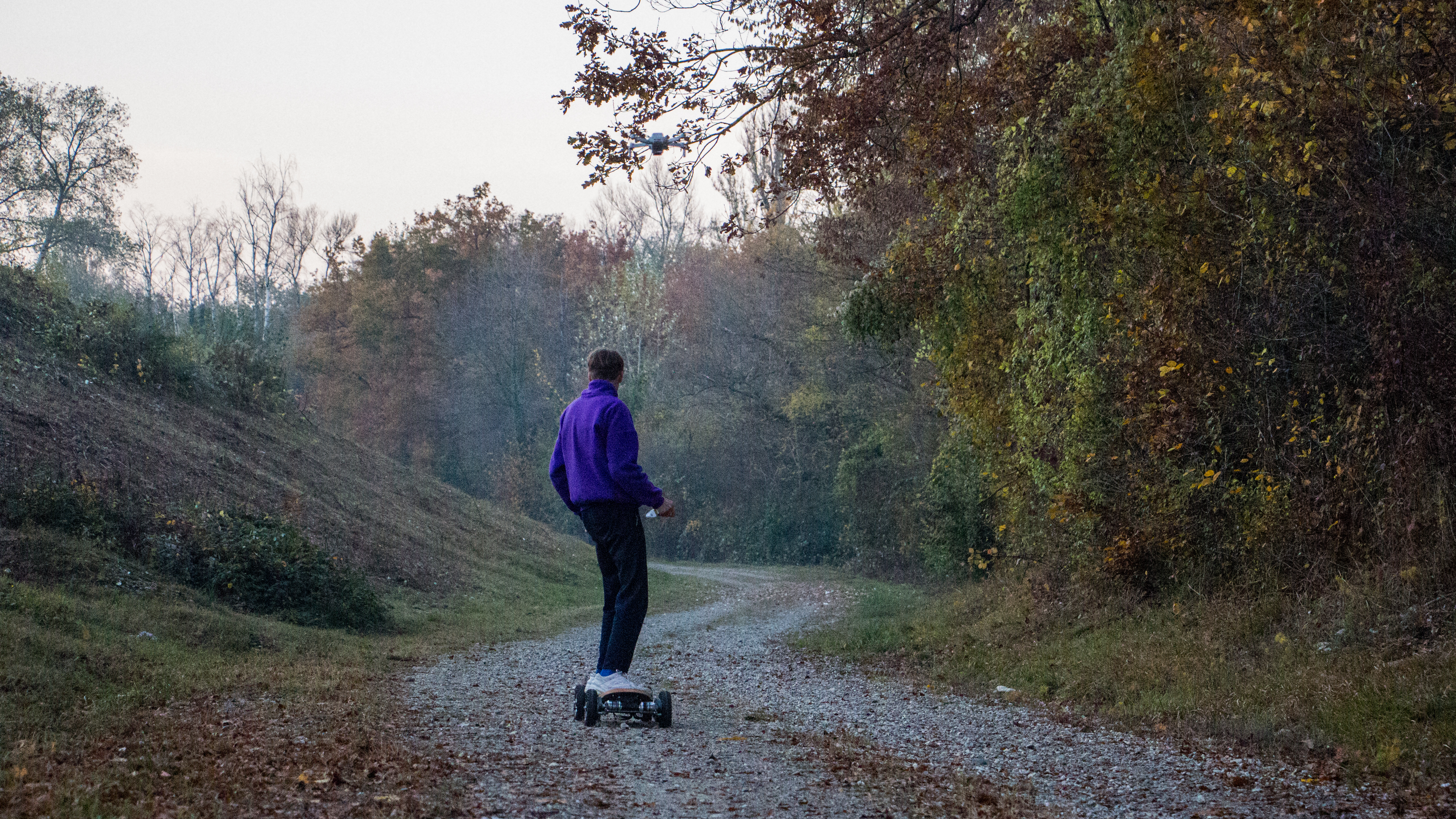
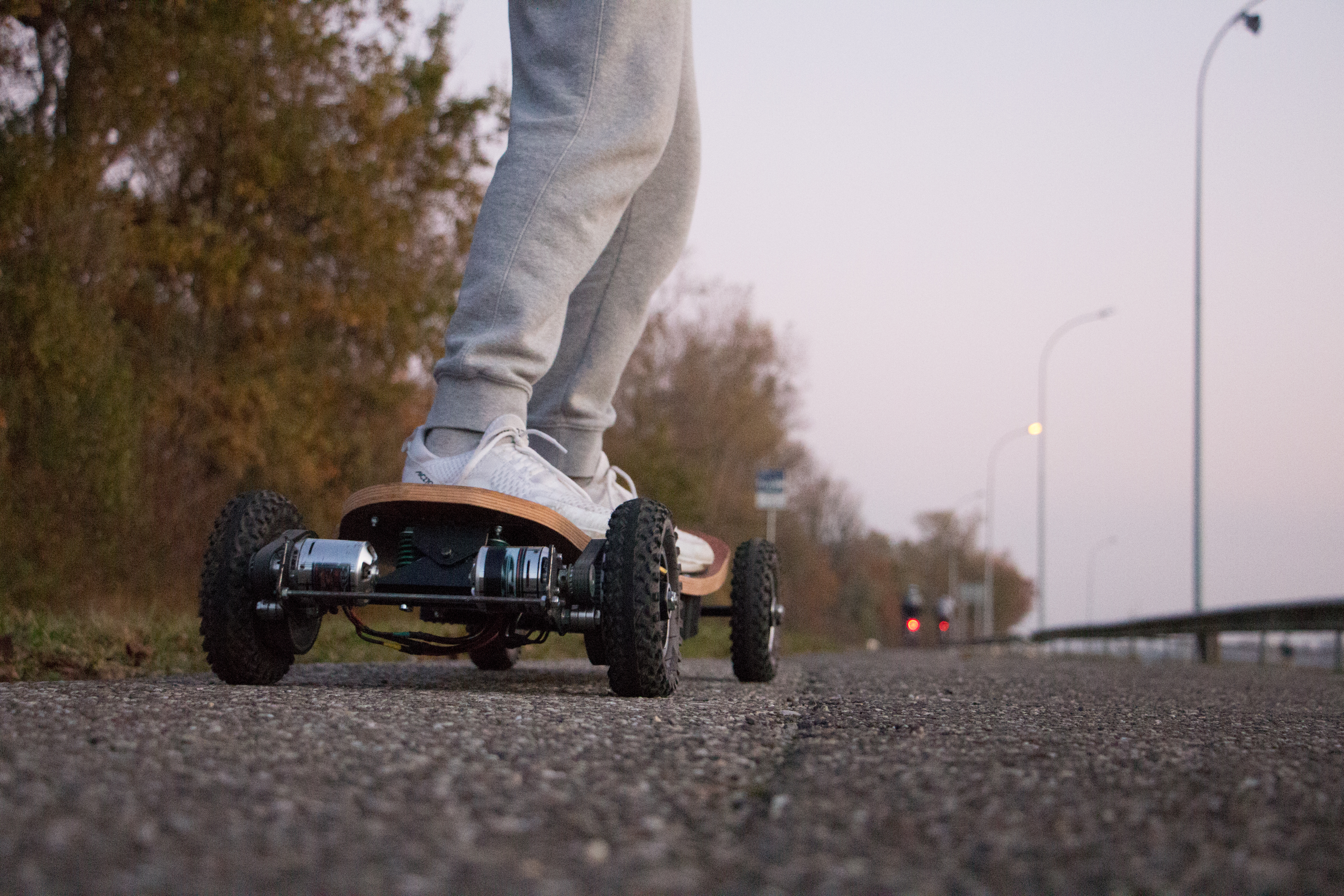
The mountainboard is the big brother of the longboard. And if you don’t know what a longboard is, it’s basically an 80 cm long wooden board with four wheels underneath. In my case, I wanted an electric assistance to be able to cruse on ruth terrain but also on regular roads. Thanks to a WIFI remote controller I can adjust the speed and the brake.
Steps
The board and the trucks
The board is made from four plywood sheets glued together. To make sure the board will hold my weight, I preferred over sizing the thickness.
Before gluing the 4mm plywood sheets together, I had to cut them a bit bigger than the mountain board’s dimensions. Once the four sheets are pre-cut it’s necessary to put them in a water bath for 24 hours.
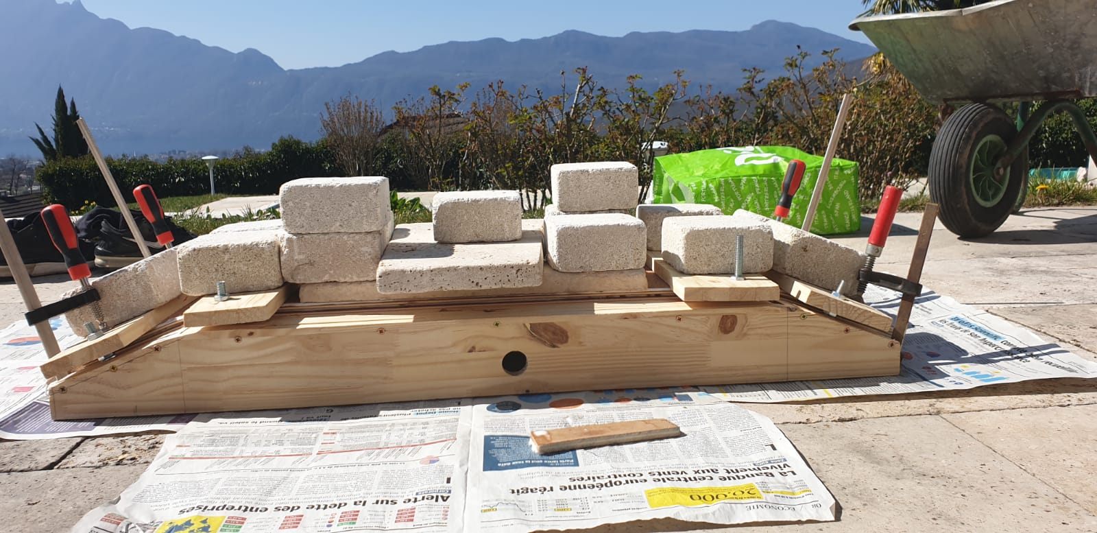
I took this time to fabricate the “gluing mold”. This mold will maintain the four plywood sheets in the wright shape while gluing.
24 hours later it is time to put all the plywood sheet in the mold as well as a huge amount of wood glue between the sheets. Of course, it’s necessary to clamp everything down using clamps and all the weight you can found in your garden.
The trucks are a precise and strong part of the mountain board. That for, I’ve used steel scare tubes and a threated rod. To create a pivot point, I’ve used a M6 screw. To keep the truck centred, two springs are required each side of the pivot point.
I would like to apologise to any professional welder which might feel insulted by seeing these horrible welds!
The battery packs
Since I want a big autonomy, I need a big battery pack.
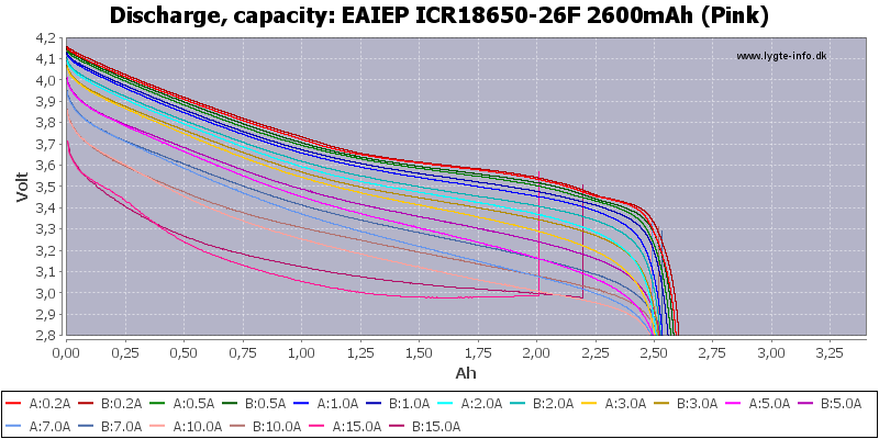
I had the choice between so many different battery types, but I’ve chosen the lithium-ion 18650 because of their reliability and their ease of use. The 18650 cells also have a decent capacity as well as a correct discharge capacity. The nominal voltage sits at 3.7V for any 18650 cell and in my case the capacity rises to 2600mAh. I’ve found the graph below showing the discharge depending on the current applied to the cell.
Since I want a big autonomy, I need a big battery pack.
To configure the final battery pack, As I already know what motor I will use, I know its rotation per volts (Kv rate), in my case it is 213Kv. After a little bit of math, we can calculate the rpm of the motor by multiplying the Kv rate by the voltage. For 30V the motor will turn faster than 6500rpm which is fast enough.
Now I know that I need a battery pack capable of delivering 30V. As 3.7V is the nominal voltage of an 18650 cell, I need eight cells in series to generate 30V.
Concerning the autonomy, I’ve had a great scientifical approach: put as many cells you can fit in the pack.
To connect the cells together, it is recommended to use an appropriate spot-welder, however I don’t have this tool so I simply soldered the cells using a soldering iron and nickel strips. Once all the cells are connected, it is time to connect the battery management system, also known as a BMS. (battery photo)
The BMS is a circuit board which balances the cells of the battery pack. While charging a battery pack, it is necessary to charge each cell at the same voltage and at the same time. If one cell has a higher voltage then another, it might damage the hall pack.
There for I’m using a battery management system. This device is used to charge equally multiple cells connected in parallel. The BMS also cuts the power off the power when the pack is low and also prevents over charging.
Propultion system
As mentioned previously, I’m using two 213KV motors so at 30V they spin at 6500rpm. This is spinning way too fast that’s why I’m using a 4 to 1 belt reduction ratio. We can now divide 6500rpm by 4 to have the wheels rpm (1625rpm).
There are different options to control the motors. First the regular electronic speed controllers, they work fine but aren’t programable. After, there is the VESC which can be programmed thanks to the VESC TOOL software. I’ve chosen this VESC for its power (100A) and its low price.
Wifi controlling system
To control the board, I could use a regular transmitter and receiver. But since I wanted to keep the budget low, I’ve maid my own WIFI remote controller. This sounded a little tricky but my neighbour helped me a lot.
I decided to use two ESP32 boards. The first one will act as a router (transmitter) and the second one the client (receiver).
For an enclosure for all the electronics, I used a WII nuchuck that I redesigned at my taste to fit all the components inside
The nunchuck’s joystick is sending an analog signal to the ESP32. The ESP32 microcontroller processes the data and send it.
I decided to use two ESP32 boards. The first one will act as a router (transmitter) and the second one the client (receiver).
The finished product
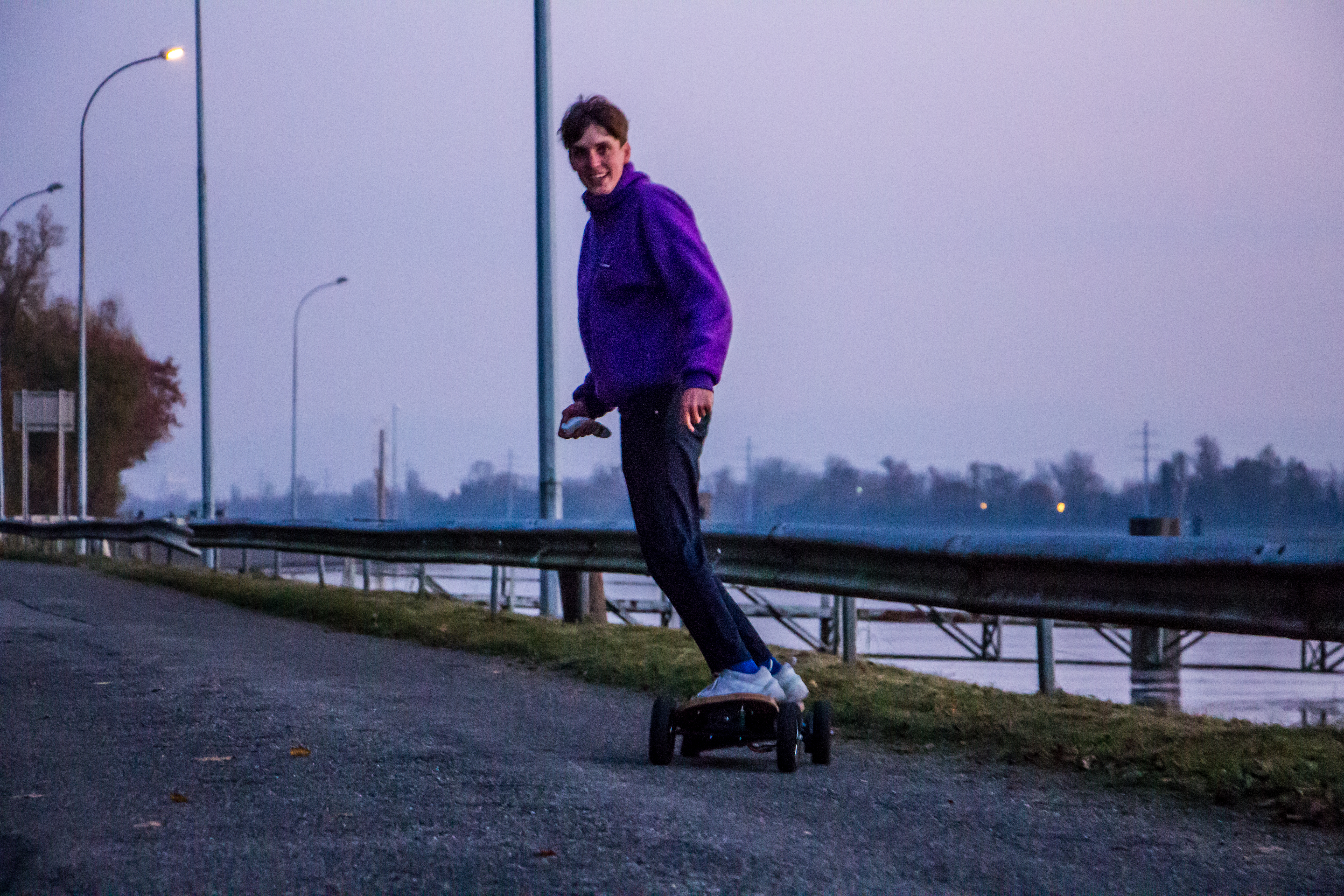
After a few years of use, I can think about some improvements that can be done.
- I want to add hall effect sensor to the motors. This will help for a smooth start and low speeds.
- The batteries have to be changed. I went with an economical option so the cell life is short. I would like to upgrade to lithium polymer.
